Grid reverse flow
Solution
Country
Europe
France
In France, there has been a sharp increase in gas consumption on the transmission network since 2017 (+4.6 percent).
The contributing factor to this increase has been the increase in gas demand from the industrial market (+10.7 percent in 2017) for electricity generation, chemical, agribusiness, and metallurgy.
Injections of biomethane into gas grids have doubled, and to avoid saturation and subsequent leakage of excess gas, a number of solutions such as temporary storage and the reverse flow technique (Grid reverse flow) have been arranged.
Read more
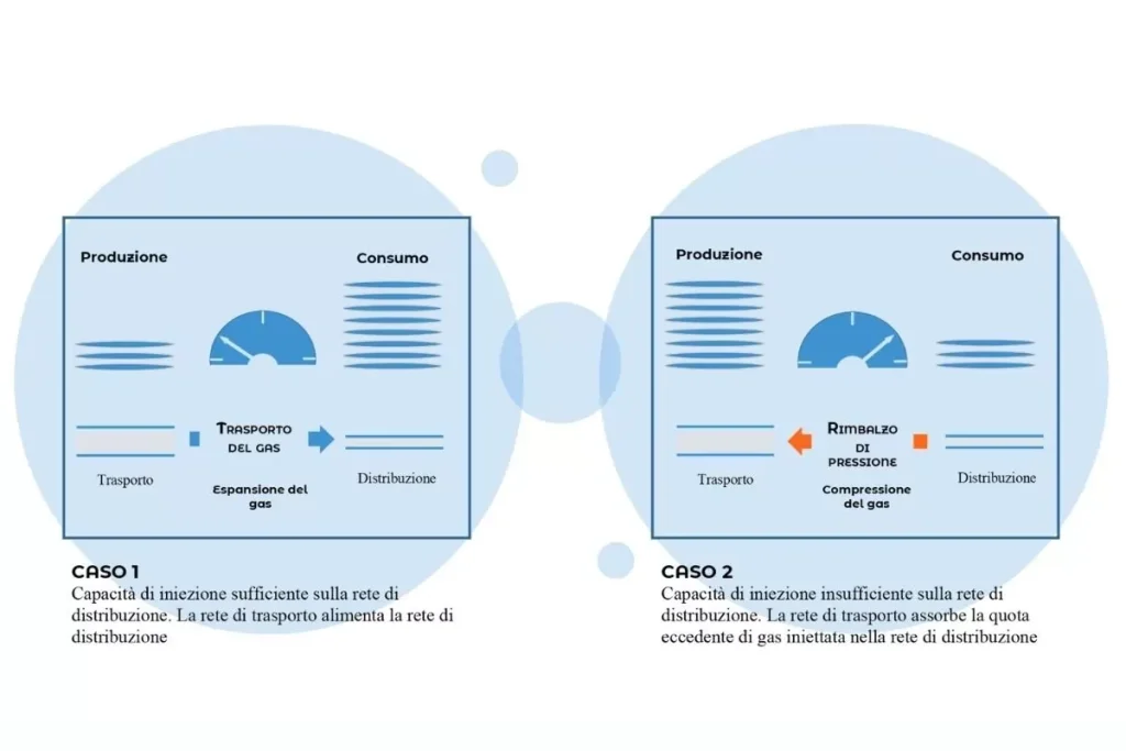
The inversion technique involves compressing unconsumed biomethane on a distribution network and then injecting it into the higher pressure network. This allows the biogas to be piped to a more distant consumption area, avoiding burning or venting to the atmosphere.
Its operation is automatic: when the network pressure reaches a high threshold (a consequence of low consumption), the compressor unit automatically kicks in; by compressing the biomethane it causes the pressure to increase and the excess to be piped into another network allowing the initial network pressure to be reduced until the minimum threshold is reached on which the compressor will stop.
These compressor plants make it possible to maximize the efficiency of the entire energy system because, through a play of pressure surges, they encourage the circulation of any surplus gas to upstream networks for immediate consumption or, otherwise, to storage units for future consumption.
Operational versatility and high performance
SV and SW compressor units provide a wide operating range with continuous flow rate adjustment (0-100%) due to VFD and recirculation line. High performance even under variable network conditions.
| Site 1 | Site 2 | Site 3 | Site 4 | Site 5 | Site 6 | Site 7 | Site 8 | |
| Pin (barG) | 3,9 | 4 | 7,5 | 4 | 8 | 7 | 8 | 4 |
| Puot (barG) | 55 | 67,7 | 60 | 67,7 | 67,7 | 67,7 | 67,7 | 67,7 |
| Flow rate (Nm3/h) | 540 | 1,450 x2 | 820 | 1,000 | 1,500 | 1,000 | 3,000 | 1,500 |
| Temp in (°C) | 15 | 15 | 15 | 15 | 15 | 15 | 15 | 15 |
| ME power (kW) | 110 | 250 x2 | 110 | 200 | 250 | 200 | 450 | 315 |
Advanced security and dedicated control
Compressors are installed in soundproof, weatherproof steel enclosures equipped with fire and gas leak detection systems. The control panel is isolated in a separate room to maximize safety.
Zero-emission gas recovery
An automatic compression unit goes into operation when pressure thresholds are exceeded, recovering any leaks and preventing leakage to the atmosphere. It operates over a wide range of pressures, reducing environmental impact.
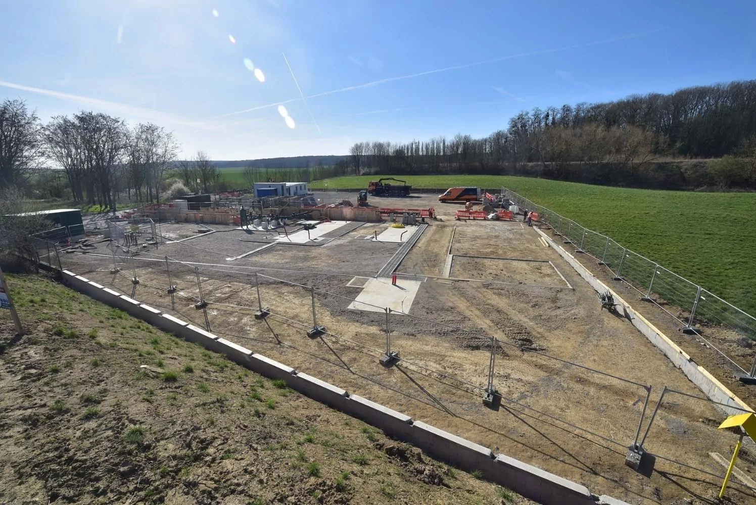
Project Requirements
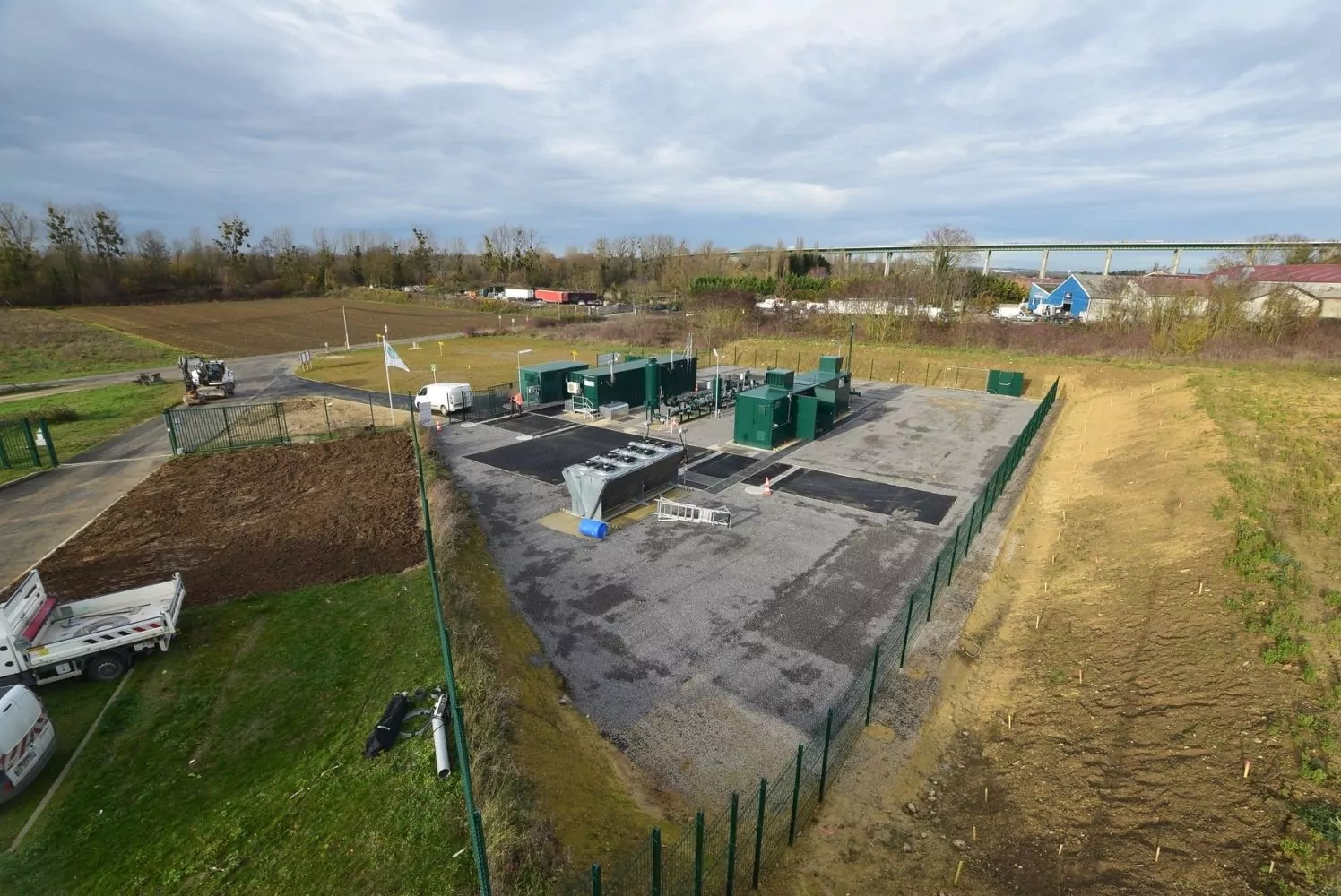
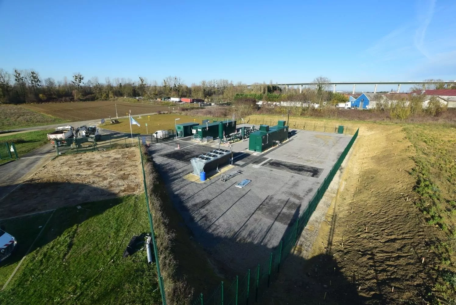
SAFE supplied 8 highly engineered plants with the following features:
Operational versatility and high performance of the compressor unit
The compression units, consisting of 2 SV and 6 SW-with direct coupling to the electric motor-operate over a wide pressure range with high efficiency. In addition, 0-100% regulation of flow rate is ensured through the combination of VFD and recirculation line.
Read more
Along with the compressor unit, SAFE provided a series of auxiliary systems designed to provide the following benefits:
Maximum flexibility and availability of the solution thanks to:
– Manual gas drying systems (found in 2 of the 8 stations) which, installed upstream of the compressor unit, clean and dry the gas when the water content of the network is too high.
– Water gas cooling systems that cool the gas at each compression stage.
High levels of safety:
Compressor units are installed inside soundproofed, weatherproof steel cabinets, the size of which varies according to the reference station. Such cabinets are equipped with a gas leak and fire detection system. To ensure maximum safety, the control panel, which manages both the power and the compressor unit, is designed and installed in a separate room from the mechanical unit.
Zero emissions:
Plants can have a compressor unit (from another OEM) with an installed capacity of 2.2 kW and a maximum flow rate of 3 Nm3/h. Such a compressor unit operates over a wide range of pressures in both suction (10 to 500 mbarG) and discharge (40 to 67.7 barG). Its operation is automatic and controlled by the control panel built into the system: whenever the inlet gas exceeds a pressure of 200 mbarG, the compression unit is activated, recovering any gas leaks and thus avoiding leakage into the atmosphere. Once the gas pressure is reduced to 10 mbarG, the compression unit stops.
Gallery /